

목차
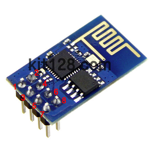
WIFI 모듈
- ENC28J60 IC가 내장된 무선 통신 모듈
- AVR,PIC 등의 MCU, Arduino 등 시리얼 통신이 가능한 모든 제품에서 사용가능
특징
- 802.11 b / g / n
- Wi-Fi Direct (P2P), soft-AP
- Built-in TCP / IP protocol stack
- Built-in TR switch, balun, LNA, power amplifier and matching network
- Built-in PLL, voltage regulator and power management components
- 802.11b mode + 19.5dBm output power
- Built-in temperature sensor
- Support antenna diversity
- off leakage current is less than 10uA
- Built-in low-power 32-bit CPU: can double as an application processor
- SDIO 2.0, SPI, UART
- STBC, 1×1 MIMO, 2×1 MIMO
- A-MPDU, A-MSDU aggregation and the 0.4 Within wake
- 2ms, connect and transfer data packets
- standby power consumption of less than 1.0mW (DTIM3)
AT COMMAND
모든 명령에는 공백(스페이스) 없이 다 붙여 써야 합니다.
| Commands | Description | Type | Set/Execute | Parameters and Examples |
|---|---|---|---|---|
| AT | general test | basic | – | – |
| AT+RST | restart the module | basic | – | – |
| AT+GMR | check firmware version | basic | – | – |
| AT+CIOBAUD | baud rate | basic | – | AT+CIOBAUD? AT+CIOBAUD=9600 AT+CIOBAUD=115200 |
| AT+CWMODE | wifi mode | wifi | AT+CWMODE=<mode> | 1= Sta, 2= AP, 3=both, Sta is the default mode of router, AP is a normal mode for devices |
| AT+CWJAP | join the AP | wifi | AT+ CWJAP =<ssid>,< pwd > | ssid = ssid, pwd = wifi password |
| AT+CWLAP | list the AP | wifi | AT+CWLAP | |
| AT+CWQAP | quit the AP | wifi | AT+CWQAP | |
| AT+ CWSAP | set the parameters of AP | wifi | AT+ CWSAP= <ssid>,<pwd>,<chl>, <ecn> | ssid, pwd, chl = channel, ecn = encryption; eg. Connect to your router: AT+CWJAP=”www.electrodragon.com”,”helloworld”; and check if connected: AT+CWJAP? |
| AT+CWLIF | check join devices’ IP | wifi | AT+CWLIF | |
| AT+ CIPSTATUS | get the connection status | TCP/IP | AT+ CIPSTATUS | <id>,<type>,<addr>,<port>,<tetype>= client or server mode |
| AT+CIPSTART | set up TCP or UDP connection | TCP/IP | 1)single connection (+CIPMUX=0) AT+CIPSTART= <type>,<addr>,<port>; 2) multiple connection (+CIPMUX=1) AT+CIPSTART= <id><type>,<addr>, <port> | id = 0-4, type = TCP/UDP, addr = IP address, port= port; eg. Connect to another TCP server, set multiple connection first: AT+CIPMUX=1; connect: AT+CIPSTART=4,”TCP”,”X1.X2.X3.X4″,9999 |
| AT+CIPMODE | set data transmission mode | TCP/IP | AT+CIPMODE=<mode> | 0 not data mode, 1 data mode; return “Link is builded” |
| AT+CIPSEND | send data | TCP/IP | 1)single connection(+CIPMUX=0) AT+CIPSEND=<length>; 2) multiple connection (+CIPMUX=1) AT+CIPSEND= <id>,<length> | eg. send data: AT+CIPSEND=4,15 and then enter the data. |
| AT+CIPCLOSE | close TCP or UDP connection | TCP/IP | AT+CIPCLOSE=<id> or AT+CIPCLOSE | |
| AT+CIFSR | Get IP address | TCP/IP | AT+CIFSR | |
| AT+ CIPMUX | set mutiple connection | TCP/IP | AT+ CIPMUX=<mode> | 0 for single connection 1 for multiple connection |
| AT+ CIPSERVER | set as server | TCP/IP | AT+ CIPSERVER= <mode>[,<port> ] | mode 0 to close server mode, mode 1 to open; port = port; eg. turn on as a TCP server: AT+CIPSERVER=1,8888, check the self server IP address: AT+CIFSR=? |
| AT+ CIPSTO | Set the server timeout | AT+CIPSTO=<time> | AT+CIPSTO? | |
| +IPD | received data | For Single Connection mode(CIPMUX=0): + IPD, <len>: For Multi Connection mode(CIPMUX=1): + IPD, <id>, <len>: <data> |
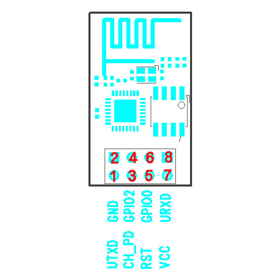
핀 맵
- 8핀이며 보드에 표기되어 있습니다.
| 좌측 핀번호 | 핀명 | 기능 | 우측 핀번호 | 핀명 | 기능 |
|---|---|---|---|---|---|
| 1 | UTXD | TXD(3.3V) | 2 | GND | Ground |
| 3 | CH_EN | ENABLE | 4 | GPIO2 | GPIO2 |
| 5 | RST | RESET | 6 | GPIO0 | GPIO0 |
| 7 | VCC | 3.3V | 8 | URXD | RXD(3.3V) |
WAT-Arduino128에 연결
WAT-Arduino128 와 ESP8266 Wifi Module 간의 연결 예입니다.
| 좌측 핀번호 | WAT-Arduino128 핀 번호 | 우측 핀번호 | WAT-Arduino128 핀 번호 |
|---|---|---|---|
| 1 | PD2(RXD) | 2 | GND |
| 3 | 3.3V | 4 | No Connect |
| 5 | PD0 | 6 | No Connect |
| 7 | 3.3V | 8 | PD3(TXD) |
예제
| 예제명 | URL |
|---|---|
| WIFI로 TCP/IP 로 서버 시간 가져오기 | https://docs.whiteat.com/?p=675 |
| ESP8266 Mode 변경 | https://docs.whiteat.com/?p=2617 |
| WIFI로 컴퓨터에서 LCD제어 | https://docs.whiteat.com/?p=808 |
제품 구매
https://kit128.com/goods/view?no=63 에서 구매하실 수 있습니다.
