

목차
[WAT-STM32-2.8] 12번 예제 RCC 헤더파일
WAT-STM32-2.8 예제 중 12번째로 RCC 헤더 파일을 사용하는 예제입니다.
주요 코드
RCC.h, RCC.c 헤더파일을 생성하여 RCC 기능을 분리하였습니다.
#ifndef __RCC_H
#define __RCC_H

#define RCC_APB2Periph_AFIO              ((uint32_t)0x00000001)
#define RCC_APB2Periph_GPIOA             ((uint32_t)0x00000004)
#define RCC_APB2Periph_GPIOB             ((uint32_t)0x00000008)
#define RCC_APB2Periph_GPIOC             ((uint32_t)0x00000010)
#define RCC_APB2Periph_GPIOD             ((uint32_t)0x00000020)

typedef struct
{
  __IO uint32_t CR;
  __IO uint32_t CFGR;
  __IO uint32_t CIR;
  __IO uint32_t APB2RSTR;
  __IO uint32_t APB1RSTR;
  __IO uint32_t AHBENR;
  __IO uint32_t APB2ENR;
  __IO uint32_t APB1ENR;
  __IO uint32_t BDCR;
  __IO uint32_t CSR;
} RCC_TypeDef;


/************ RCC Adress 지정   *************/
#define AHBPERIPH_BASE        (PERIPH_BASE + 0x20000)
#define RCC_BASE              (AHBPERIPH_BASE + 0x1000)
#define RCC                 ((RCC_TypeDef *) RCC_BASE)

void RCC_init(void);

#endif
#include "main.h"
#include "rcc.h"


void RCC_init()	  // RCC_init() 함수
{
  // Clock control register
  // Bit17 HSERDY: External high-speed clock ready flag
  // Bit16 HSEON: External high-speed clock enable
  unsigned char sws = 0;
  RCC->CR |= 0X00010000; // HSEON
  while(!(RCC->CR>>17));  //HSE 준비될때까지 기다림

  // Clock configuration register (RCC_CFGR)
  // Bits21:18 PLLMUL: PLL multiplication factor
  // Bits10:8 PPRE1: APB low-speed prescaler (APB1)
  /* Bit10-8 0x100    100: HCLK divided by 2  */
  RCC->CFGR = 0x00000400;

  /*
  0000:PLL input clock x 2	  1000:PLL input clock x 10
  0001:PLL input clock x 3	  1001:PLL input clock x 11
  0010:PLL input clock x 4	  1010:PLL input clock x 12
  0011:PLL input clock x 5	  1011:PLL input clock x 13
  0100:PLL input clock x 6	  1100:PLL input clock x 14
  0101:PLL input clock x 7	  1101:PLL input clock x 15
  0110:PLL input clock x 8	  1110:PLL input clock x 16
  0111:PLL input clock x 9	  1111:PLL input clock x 16
  */

  RCC->CFGR |= 7<<18; // PLL input clock x 9 -> 72MHz
  RCC->CFGR |= 1<<16; //1: HSE oscillator clock selected as PLL input clock
    FLASH->ACR|=0x32;
  RCC->CR |= 1<<24;   //1: PLL ON

  while(!(RCC->CR>>25)); //0: PLL unlocked 기다림
  RCC->CFGR |= 1<<1;  //10: PLL selected as system clock

  while(sws != 0x2)	 // 10: PLL used as system clock
  {
    sws = RCC->CFGR>>2;	 // Bits3:2 10: PLL used as system clock
    sws &= 0x3;
  }

}
RCC 를 헤더파일로 구성하여 main.c 코드는 더 간소화 되었습니다.
// WAT_STM3228_12 RCC 헤더 파일 추가
// 1초 간격으로 LED2 ON/OFF
//
// 출처: https://docs.whiteat.com/?p=3676
//

#include "main.h"
#include "rcc.h"

#define LEDON 	  (GPIOB->BRR = GPIO_Pin_2)
#define LEDOFF 	  (GPIOB->BSRR = GPIO_Pin_2)


void LED_init()
{
   /* GPIOB Port Enable*/
  RCC->APB2ENR |= RCC_APB2Periph_GPIOB;

  /*-- GPIO Mode Configuration speed, input/output -----------------------*/
  /*-- GPIOB max speed: 50MHz , General purpose output push-pull  ---*/
	GPIOB->CRL &=  0xFFFFF0FF;
	GPIOB->CRL |=  0x00000300;
}

void Delay(vu32 nCount)		 //delay
{
  for(; nCount != 0; nCount--);
}

int main(void)
{
 	RCC_init();		//RCC 초기화
	LED_init();		//LED 초기화

  while (1)
  {
    LEDON; 		// LED ON
    Delay(0x17FFFF*5);  // delay
    LEDOFF;				  // LED OFF
    Delay(0x17FFFF*5);	  //  delay
  }
}
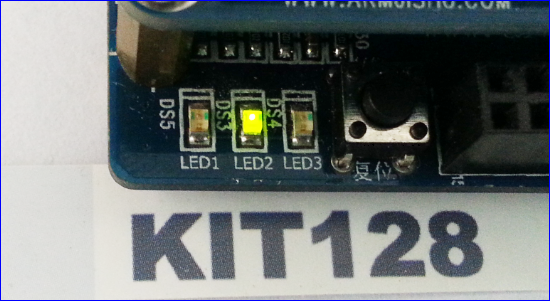
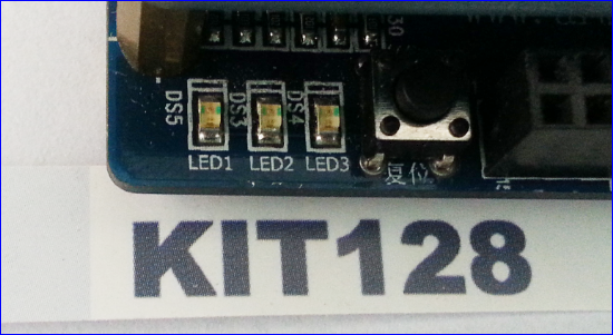
결과화면
앞의 예제와 동일하게 1초마다 ON/OFF 합니다.
WAT-STM32-2.8보드 전체 예제
제품 구매
WAT-STM32-2.8 [STM32F103RB Board + 2.8인치 TFT LCD 터치 세트] 는 https://kit128.com/goods/view?no=221 에서 구매하실 수 있습니다.

